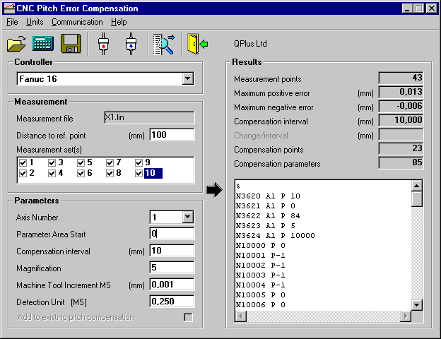
Measurement File Options
Measurement file options are the same for all the controller types. Reference point is the distance between machine tool axes reference point and the start point of the measurement. If measurement file includes several measurement runs (sets) they all are listed in a Measurement set(s) listbox. It is possible to select just one or several sets for the compensation. If more than one set is selected the average of all selected measurement sets are used for the compensation.
Parameters Options
Axis Number
Axis number specifies which axes is to be
compensated. The compensation file parameter options are
changed accordingly.
Parameter Area Offset
Parameter address offset is added to the parameter
address starting number. This is how different axes
compensation parameter areas are separated. The maximum
parameter address is 11023
Compensation Interval
Compensation interval defines how many compensation
points are needed. By decreasing the interval smaller
compensation steps are needed.
Magnification
Magnification value multiplies the used compensation
step. If the magnification is 1 then the compensation
step is the same as detection unit.
Machine Tool Increment
Machine tool increment is the used linear scale accuracy
for the machine tool. Increment can be read from a
downloaded parameter file (N1004).
Detection Unit
Detection unit is the unit by which compensation is made.
So if the detection unit is 0.00025 mm and compensation
is 2 and magnification is 5 then compensation at that
point is 0,00025 * 2 * 5 = 0,0025
Add to existing pitch compensation
If existing pitch compensation file is read from NC, the
new compensation can be actualised cumulative to old
ones. If you want to measure and compensate without
clearing the old compensations, read first the old values to PC,
put a cross in this selection and measure machine tool
compensations set active.
With this controller type, it is possible to read the current machine tool increment system from a file, if the current parameter area is downloaded from the controller. Parameter N1004 bit 7 and 8 defines the machine tool increment system in a following matter:
| Bit | Machine tool | Increment |
| 00 | IS-B | 0,001 |
| 10 | IS-C | 0,0001 |
| 01 | IS-A | 0,01 |
Also the Detection unit is read from the file. Detection unit is read from a parameter N1820:
If N1820 is 2-96 then Detection unit = N1004/(N1820/2)
If N1820 is 102-127 then Detection unit =
N1004/(1/(N1820-100))
Calculation
The calculation is done by pressing the CALCULATE toolbar button. Maximum value for compensation is 7 on each compensation point. If you get a message: "Compensation value over 7", you must either decrease compensation interval or increase magnification.
Results
Calculation results are shown on the right side of the form. The actual compensation file format is shown on the lower right corner of the window.
Saving the compensation parameter file
Compensation parameter file is saved by pressing the SAVE toolbar button. After this the save file dialog is opened.
Sample screen