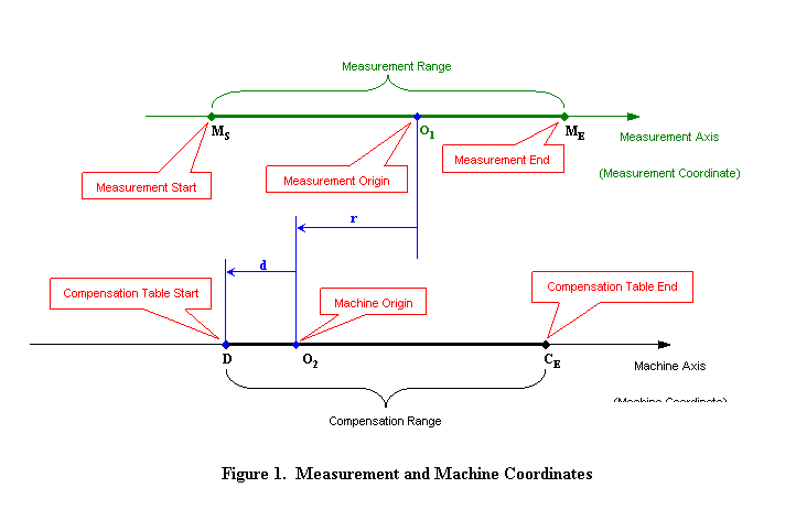
Measurement File OptionsDistance to reference point Distance to reference point controls the location of the measurement range in machine. If the position data in your measurement file are taken in machine coordinates, this value should be 0. If not, as shown in Figure 1, this value is the distance from origin of the machine O2 to the origin of measurement O1, which is value r. Please also notice that if the machine origin O2 locates at the left of the measurement origin O1 as in Figure 1, then r < 0. If the machine origin O2 locates at the right of the measurement origin O1, then r > 0. As default, the measurement range is aligned in the machine so that the machine origin O2 is overlapped with measurement start point MS. Please notice that your case can be different from the default setting.
If measurement file includes several measurement runs (sets) they all are listed in a 'Measurement set(s)' list box. It is possible to select just one or several sets for the compensation. If more than one set is selected the average of all selected measurement sets are used for the compensation.
Parameters OptionsModel Model specified the model type of the display unit.
Compensation interval Compensation interval defines distance between consecutive compensation points. For the units with software version 349797-07 or lower, interval can only be a fixed size (2^n / 1000) and thus you have to select a suitable step from predefined choices. Because amount of compensation points per table is restricted to 64, it might be sometimes necessary to increase step size. Program will inform you if this is necessary. For the units with software version 349797-08 or higher, interval can be decided freely. Program will give warning if the compensation table cannot reach the end of the measurement range with the interval (the end point of compensation table CE locates at the right of measurement end point ME).
Start of compensation table This value determines the start of compensation table in machine coordinate, which is d in Figure 1. If compensation start point D locates at the right of machine origin O2, then d > 0. If compensation start point D locates at left of machine origin O2 as in Figure 1, then d < 0. This value is also the datum in compensation table.
Parameter file If existing parameter file is read in, the file name is displayed accordingly.
Compensation file If existing pitch compensation file is read in, the file name is displayed accordingly.
Add to existing pitch compensation If existing pitch compensation file is read in, the new compensation can be actualised cumulative to old ones. If you want to measure and compensate without clearing the old compensations, first read in the old values, then check this selection and carry out measurements so that compensations are set active in a machine tool.
CalculationThe calculation is done by selecting File/Calc menu, pressing the CALCULATE toolbar button or press the arrow sign in the middle of the screen.
ResultsCalculation results are shown on the right side of the form. The actual compensation file format are shown on the lower right corner of the window.
Saving the compensation parameter fileCompensation and parameter files are saved by pressing the SAVE toolbar button. After this first the saving compensation file dialog is opened. It asks for name of compensation file. After the compensation file name is given and confirmed, if an existing parameter file has been read in, the saving parameter file dialog is opened, asking for parameter file name to be save. After the compensation file and/or parameter file are saved, information are displayed accordingly.
Automatically send compensation fileNote: This function is only available with software version 349797-08 or higher. Please check the backside of the display unit for its software version.
Sample screen
|
